400G SR4 vs. DR4 vs. FR4 vs. LR4: A Practical Guide to Choosing the Right Optical Transceiver
Data center operators upgrading to 400G face a familiar challenge: the transceiver options all promise 400 Gbps, yet each is engineered for a different combination of distance, fiber type, and connector. Choosing the wrong one wastes budget at best and breaks the link budget at worst. This guide breaks down the four most common 400G transceiver types—SR4, DR4, FR4, and LR4—and explains where each belongs in a modern network architecture.
Understanding the 400G Naming Conventions
Before comparing specifications, it helps to decode the letters and numbers in these model names. The prefix—SR, DR, FR, or LR—maps directly to the reach class defined by IEEE and the 100G Lambda MSA. “SR” stands for Short Reach, “DR” for Distance Reach (500 meters), “FR” for Far Reach (2 kilometers), and “LR” for Long Reach (10 kilometers). The number “4” in each model indicates four optical lanes, each carrying 100 Gbps via PAM4 modulation to reach an aggregate 400 Gbps. This four-lane parallel architecture is what separates these modules from older NRZ-based designs and enables the bandwidth density that modern spine-leaf fabrics demand.
Fiber Type and Connector: The First Decision Point
The single most important variable in transceiver selection is the fiber plant you already have or plan to deploy. 400G SR4 runs over multimode fiber (MMF) with a center wavelength of 850 nm and an MPO-12 connector, reaching up to 100 meters on OM4 fiber. It is the natural choice for intra-rack and top-of-rack connections where MMF is already installed, and its lower power draw (around 8.5W) makes it attractive in dense rack environments.
400G DR4 shifts to single-mode fiber (SMF) with a 1310 nm wavelength and an MPO-12 APC connector, extending reach to 500 meters. This makes it the workhorse for spine-leaf links in large data halls where distances exceed what MMF can reliably support. The critical detail with DR4 is its parallel lane structure: four separate SMF strands carry four independent 100G signals, so fiber counts matter when planning patch panels.
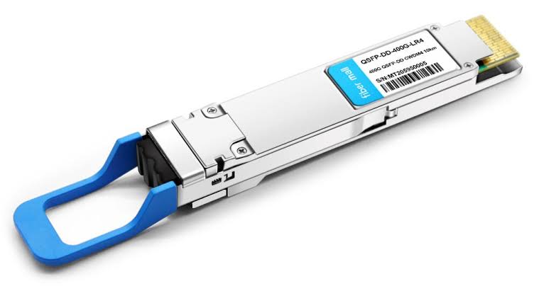
400GBASE-FR4 and 400GBASE-LR4 both use duplex LC connectors and wavelength-division multiplexing to reduce fiber consumption dramatically. FR4 combines four CWDM wavelengths (1271, 1291, 1311, and 1331 nm) onto a single fiber pair, delivering 2 km of reach over SMF. LR4 follows the same four-lane approach but uses LAN-WDM wavelengths optimized for longer transmission, supporting up to 10 km. In campus or metro DCI scenarios where fiber availability is limited, these duplex-LC modules can save hundreds of fiber strands compared to parallel-optics alternatives.
Standards, Power, and Breakout Considerations
Each 400G variant is governed by a specific IEEE standard. The 400G BASE-FR4 specification, defined under IEEE 802.3cu, targets four-wavelength 400 Gb/s operation over SMF with lengths up to at least 2 km. DR4 falls under IEEE 802.3bs, while SR4 aligns with 400GBASE-SR4 and related MMF standards.
Power consumption varies meaningfully across the family. SR4 modules typically consume around 8.5W, DR4 around 8–10W, and FR4 and LR4 closer to 12W. In a 32-port switch, that difference accumulates quickly and directly affects thermal design and cooling costs.
Breakout capability is another differentiator. DR4 and SR4 modules can often be configured as 4x100G breakout links, connecting a 400G port to four 100G ports on downstream devices. This is invaluable during phased migrations from 100G to 400G infrastructure, allowing operators to protect existing investments while building toward higher density. FR4 and LR4, by contrast, are typically used as native 400G links without breakout.
Matching the Module to the Application
The practical selection framework comes down to three questions: How far? Over what fiber? And with what connector budget?
For intra-rack connections under 100 meters, 400G SR4 remains the cost-effective standard. It leverages existing MMF cabling and delivers reliable performance without the complexity of wavelength multiplexing.
For spine-leaf links between 100 and 500 meters, 400G DR4 is the logical choice. Its 500-meter reach covers the vast majority of leaf-to-spine spans in hyperscale and enterprise data centers, and its parallel SMF architecture avoids the insertion loss that WDM introduces.
For campus DCI and cross-building links up to 2 km, 400G FR4 offers the best balance of reach, fiber efficiency, and cost. The duplex LC interface means a single fiber pair carries the full 400 Gbps, which simplifies cable management and reduces patch-panel congestion. Many AI training clusters now standardize on FR4 for exactly this reason—the 2 km reach covers most GPU cluster topologies without repeaters.
For metro-area links between 2 and 10 km, 400G LR4 becomes necessary. Its LAN-WDM wavelength grid and EML-based transmitter design handle the greater chromatic dispersion that accumulates over longer distances.
It is also worth noting that not every network runs exclusively at 400G. Legacy 10G BiDi SFP+ modules remain widely deployed for single-fiber, bidirectional 10G links in access and aggregation layers, using a simplex LC connector and paired 1270/1330 nm wavelengths to reach 10 km over OS2 single-mode fiber. These modules illustrate the same principle that governs 400G selection: match the optical interface to the fiber availability and distance requirement, nothing more and nothing less.
Conclusion
The 400G transceiver family is not a hierarchy of better or worse options—it is a toolkit. SR4 handles the shortest MMF runs, DR4 bridges the mid-range SMF gap, FR4 optimizes fiber efficiency at 2 km, and LR4 extends reach to 10 km. The right choice depends entirely on the physical layer you are building on. Start with fiber type and distance, confirm the IEEE standard your switch platform supports, and let connector and power constraints guide the final decision.